 by
by Definition of Electromagnetic induction
Whenever magnetic flux linked with a coil changes , an EMF is induced in it . This phenomenon is known as electromagnetic induction .
Electromagnetic induction is the phenomenon due to which an electric current is induced in a coil due to a changing magnetic field or due to relative motion between a coil and a magnet , an EMF is induced in the coil .
Magnetic flux;-
It is the number of magnetic lines of force passing through a coil perpendicularly placed in a magnetic field .
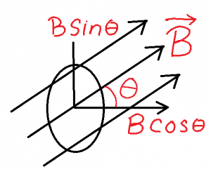
Let a coil of cross sectional area A be placed in a uniform magnetic field B , such that the normal of the coil makes an angle θ with the direction of the magnetic field . Resolving B we have
(i) B cosθ along the normal of the coil
(ii) B sinθ along the surface of the coil
Since B cos theta is responsible for the calculation of magnetic flux through the coil , so according to the definition magnetic flux passing to the coil
ϕ = B cos x S = BS cos
=
CGS unit of magnetic flux = maxwell
SI unit of magnetic flux = weber
dimensional formula of magnetic flux = [M1L 2T -2A-1]
Faraday’ laws of Electromagnetic induction:-
(I) Whenever magnetic flux linked with a coil changes , an emf is induced in it , which lasts so long as the change in magnetic flux continues through the coil .
(II) The emf induced in the coil is directly proportional to the rate of change of magnetic flux linked with it .
Expression for induced emf :-
Let in a small time interval ∆t , magnetic flux linked with the coil changes by ∆ϕ .
Rate of change of magnetic flux =
According to Faraday’s law , emf induced in the coil ,
e ∝ = > e = K
………………(1)
According to Lenz , K = – 1
So , e = – ……………..(2)
In differential form e = – ………(3)
If ϕ1 be the initial magnetic flux linked with the coil which becomes ϕ2 , after a time interval of t , then emf induced in the coil becomes ,
Lenz’s law:-
” The direction of the induced current in a coil due to change in magnetic flux , is such that it tries to oppose the cause creating it .”
Q- Prove that Lenz’s law is obeying the principle of conservation of mechanical energy. Or , Explain the origin of the induced emf .
Ans –
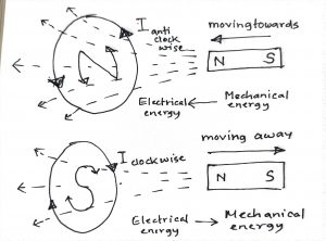
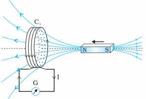
When the north pole of a bar magnet is pushed towards a coil , the face of the coil facing the magnet acquires north polarity , োccording to Lenz’s law . So work is to be done by the magnet to move it further against the force of repulsion at cost of mechanical energy stored in it , which will appear as the electrical energy of the coil .
When the north pole of the magnet is moving away from the coil , the same face acquires south polarity. Now the work is done by the coil at cost of electrical energy store in it , which will reappear in the magnet as its mechanical energy .
Thus conversion of energy from one form to another and vice versa confirms that Lenz’s law is the obeying the principle of conservation of mechanical energy . This is the origin of the induced emf in the coil , due change in magnetic flux .
Self induction :-
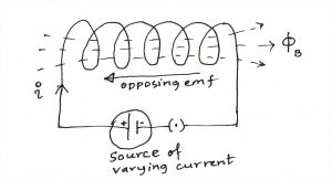
Self induction of the coil is the phenomenon by virtue of which an opposing emf is induced in it , when the current flowing through it changes .
Expression for self inductance or coefficient of self induction of a coil :-
Let at any instant , I be the current flowing through a coil due to which ϕ amount of magnetic flux is linked with the coil .
It is seen that , ϕ ∝ I => ϕ = LI …(1) where L be the self inductance or coefficient of self induction of the coil
If I = 1A , => ϕ = L x l => L = ϕ
Therefore, coefficient of self induction of a coil is numerically equal to the magnetic flux linked with a coil when unit current flows through it.
According to laws of electromagnetic induction ,
if , ,
then |e| =L ……….(2)
The coefficient of self induction or self inductance of a coil is numerically equal to the magnitude of the opposing emf induced in the coil when current in the coil is changing at the unit rate .
The SI unit of self Inductance is henry (H)
We know
, ….(1)
If |e| = 1 volt and ,
then L = 1 henry
The self-inductance of a coil is said to 1 henry , if due to a current changing at the rate of 1 A/s induces an opposing emf of 1 volt in it .
Dimensional formula of self inductance :-
Expression for self inductance of a solenoid :-
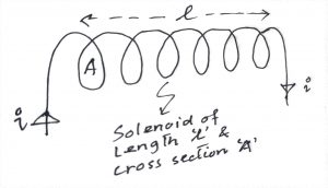
Let us consider a solenoid of length l and area of cross section A with N turns carrying I amount of current . If B is the magnetic field at any point inside the solenoid along its axis , then ……………(1)
Magnetic flux per turn of the solenoid , …..(2)
So total magnetic flux linked with the solenoid ,
…(3)
If L is the coefficient of self induction of the solenoid, then by its definition , ϕ = LI ….(4)
Comparing (3) & (4) , ….(5)
L primarily depends on the number of turns as compared to the magnitude of other terms , it is very large .
Energy associated with an inductor or coil & its energy density :-
Whatever current flows through a coil, the self-inductance opposes the growth of the current. Hence, some work has to be done by external agencies in establishing the current . If e is the induced emf then ………..(1)
Again by definition of potential difference , ……………(2)
From (1) & (2) …..(3)
The total work done when the current Increases from 0 to maximum value I0 is ………..(4)
This work done is stored as magnetostatic potential energy of the coll. …….(5)
Energy density of a coil is the energy stored per unit volume of it .
If A be the cross section of the solenoid of length l , then its energy density …(1)
We know , self induction of the solenoid , ……..(2)
Magnetic field along the axis of solenoid , …..(3)
(1)=> …………….(4)
Fleming’s right hand rule
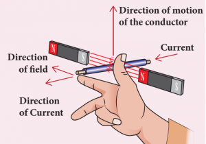
The thumb, index finger or the first finger and middle finger or central finger of right hand are stretched out in mutually perpendicular directions . If the index finger points the direction of the magnetic field and the thumb indicates the direction of
motion of the conductor or the force , then the middle finger will indicate the direction of the induced current.
Motional EMF or emf induced in a rod moving in a magnetic field :-
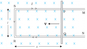
Let us consider a a rectangular conductor PQRS in which the conductor PQ = L is free to move , placed in a uniform magnetic field B , acting perpendicularly inward the plane of paper .
Let the rod PQ be moved towards the left with a constant velocity v and at any instant , RQ = x
The magnetic flux ΦB enclosed by the area PQRS is , ΦB = B x area PQRS = B l x …(1)
Since x is changing with time, the rate of change of flux ΦB will induce an emf in PQ , so according to Faraday’s law emf iduced in it – …….(2)
By Flemming’s right hand rule , current will flow from end P to Q along the conductor PQ
So the conductor PQ is equivalent to a cell generating emf e = Blv = VQ – VP , called motional emf .
So , end Q will be at higher potential and end P will be at lower potential .
Rotational EMF or EMF induced in a rod rotating uniformly in uniform magnetic field :-
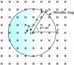
Let a rod of length L be rotating with uniform angular velocity ω inside a ring , placed perpendicularly in a uniform magnetic field B , acting perpendicularly inward to the plane of paper .
Let in time interval t , it is rotated about end O from the position OP to OQ , such that ∠POQ = θ = ωt
Area of ΔPOQ = ½ x OP x PQ
= ½ x L x L θ
= ½ L 2 θ ….. (1) [ θ = arc PQ / radius OP = > arc PQ = θ x OP = θL]
The magnetic flux ΦB enclosed by the area OPQ is ,
ΦB = B x area OPQ
= B x ½ L 2 θ
= ½ B L 2 θ …(2)
According to Faraday’s law , emf induced in the rod ,
……(3)
By Flemming’s right hand rule , current will flow from end P to O and Q to O along the rotating conductor.
So the rotating rod is equivalent to a cell generating emf e = ½ B L 2ω = VO – VP = VO – VQ , called rotational emf .
So , end O will be at higher potential and end P and Q will be at lower potential .
Mutual Induction
The phenomenon by virtue of which an opposing emf is induced in a coil , when current in a neighbouring coil changes is known as mutual induction of the given pair of coils .
Expression for coefficient of mutual induction or mutual inductance of a pair of coils
Let P and S be the two coils very much close to each other, P being connected to a source of varying current and S being connected to a galvanometer . P is called Primary coil and S is called secondary coil.
Let at any instant , be the current in P due to which
pbe the magnetic flux in P, which is also linked to S , giving
amount of magnetic flux in S . It is seen that ,
∝
…….(1) where M is mutual inductance of the coils P and S .
By Faraday’s law opposing emf induced in the secondary coil
………………(2)
If then
, If current in the primary coil changes in the unit rate, then the magnitude of the induced emf in the secondary coil is called the coefficient of mutual induction of the given pair of the coils .
SI unit of mutual inductance of a pair of coils :- henry (H)
We know that , ….(1)
If and
, then M = 1 henry
If due to current in the primary, changing at the rate of 1A/s, induces an opposing emf of 1 Vin the secondary, then mutual inductance of the coil is said to be 1 henry .
Dimensional formula of mutual inductance :-
Expression for co efficient of mutual induction or mutual inductance of a pair of co axial solenoids
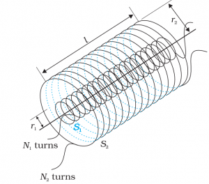
Consider two long co-axial solenoids S1 and S2 , each of length l , with n1 and n2 as the number of turns per unit length , of radius r1 and r2 as the radii , carrying time varying current i1 and i 2 respectively .
Magnetic flux through S1 due to i2 in S2 is
ϕ 1 = (n1l) ( B2 ) ( r12 )
=> 1 = (n1l) ( μ0 n2 I2 ) (
r12 )
=> 1 =
μ0 n1n2 l r12 I2 … (i)
Magnetic flux Φ1 in S1 due to S2.
∴ 1 = M12 l2 … (ii)
Where M12 is the Mutual inductance of S1 due to S2
From equations (i) and (ii), we get
M12 = μ0 n1n2 l r12 …(iii)
Similarly magnetic flux through S2 due to i1 in S1 is
2 = (n2 l) ( B1 ) (
r22 )
=> 2 = (n2l) ( μ0 n1 I1 ) (
r22 )
=> 2 =
μ0 n1n2 l r22 I1 … (iv)
By definition , magnetic flux f 2 in S2 due to S1
∴ 2 = M21 l1 … (v)
Where M21 is the Mutual inductance of S2 due to S1
From equations (iv) and (v), we get
M21 = μ0 n1n2 l r22 …(vi)
Assuming r1 ≈ r2 = r , we can write
M12 = M21 =M = μ0 n1n2 l r2 …(vii)
So M primarily depends on the product of number of turns per unit length of the two solenoids .
Eddy currents or Foucault currents –
When a metallic body moves in a magnetic field or when the magnetic field through a stationary metallic body is altered, induced current is produced in the metal. This current is called eddy current.
The direction of the eddy current is given by Lenz’s law.
Disadvantages of Eddy Current
(i) Eddy current involves excessive production of heat , causing loss of energy.
(ii) It creats wear and tear to the life of conductors .
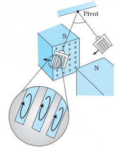
Eddy currents are minimised by using laminations of metal to make a metal core. The laminations are separated by an insulating material . The plane of the laminations must be arranged parallel to the magnetic field, so that they cut across the eddy current paths , reducing the strength of the eddy currents.
Eddy currents are used to advantage in certain applications like:
(i) Magnetic braking in trains: Strong electromagnets are situated above the rails in some electrically powered trains. When the electromagnets are activated, the eddy currents induced in the rails oppose the motion of the train. As there are no mechanical linkages, the braking effect is smooth.
(ii) Electromagnetic damping: Certain galvanometers have a fixed core made of nonmagnetic metallic material. When the coil oscillates, the eddy currents generated in the core oppose the motion and bring the coil to rest quickly.
(iii) Induction furnace: Induction furnace can be used to produce high temperatures and can be utilised to prepare alloys, by melting the constituent metals. A high frequency alternating current is passed through a coil which surrounds the metals to be melted. The eddy currents generated in the metals produce high temperatures sufficient to melt it.
(iv) Electric power meters: The shiny metal disc in the electric power meter (analogue type) rotates due to the eddy currents. Electric currents are induced in the disc by magnetic fields produced by sinusoidally varying currents in a coil.
Give the construction and working principle AC Generator.
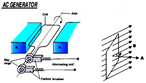
An ac generator converts mechanical energy into electrical energy.
Principle of ac generator:- By changing the loop’s orientation or changing its effective area , an emf or current is induced in the loop .
As shown in above figure , it consists of a coil mounted on a rotor shaft . The axis of rotation of the coil is perpendicular to the direction of the magnetic field. The coil (called armature) is mechanically rotated in the uniform magnetic field by some external means. The rotation of the coil causes the magnetic flux through it to change, so an emf is induced in the coil. The ends of the coil are connected to an external circuit by means of slip rings and brushes.
When the coil of area A , is rotated in the magnetic field B with a constant angular speed ω(ω = θ/t), at any instant t , the effective area of the coil is A cos θ, where θ is the angle between A and B.
So , the magnetic flux at t is ΦB = BA cos θ = BA cos ωt
From Faraday’s law, the induced emf for the rotating coil of N turns is then ,
Thus, the instantaneous value of the emf is e = NBA ω sin ωt …….(1)
where NBAω is the maximum value of the emf = E 0 , which occurs when sin ωt = ±1.
(1) => e = E 0 sin ωt ……………….(2)
The emf has its extremum value when θ = 90º or θ =270º, as the change of flux is greatest at these points.
The direction of the current changes periodically and therefore the current is called alternating current (ac).
Since ω = 2πν, Eq (2) can be written as e = E0 sin 2πν t ……….(3)
where ν is the frequency of revolution of the generator’s coil.
Eq. (2) and (3) give the instantaneous value of the emf and ε varies between +ε0 and –ε0 periodically.
Types of commercial generators
Hydro-electric generators, the mechanical energy required for rotation of the armature is provided by water falling from a height, i.e, from dams. Thermal generators water is heated to produce steam using coal or other sources. The steam at high pressure produces the rotation of the armature.
Nuclear power generators. Instead of coal, a nuclear fuel can also be used,
The frequency of rotation is 50 Hz in India.
In certain countries such as USA, it is 60 Hz.